
Guide Trough
A continuous guide path through your mill.
BOYE guide troughs provide a defined path for hot-rolled steel as it travels between mill equipment and through cooling sections. The arrangement depends on the product size, pass line and installation position.
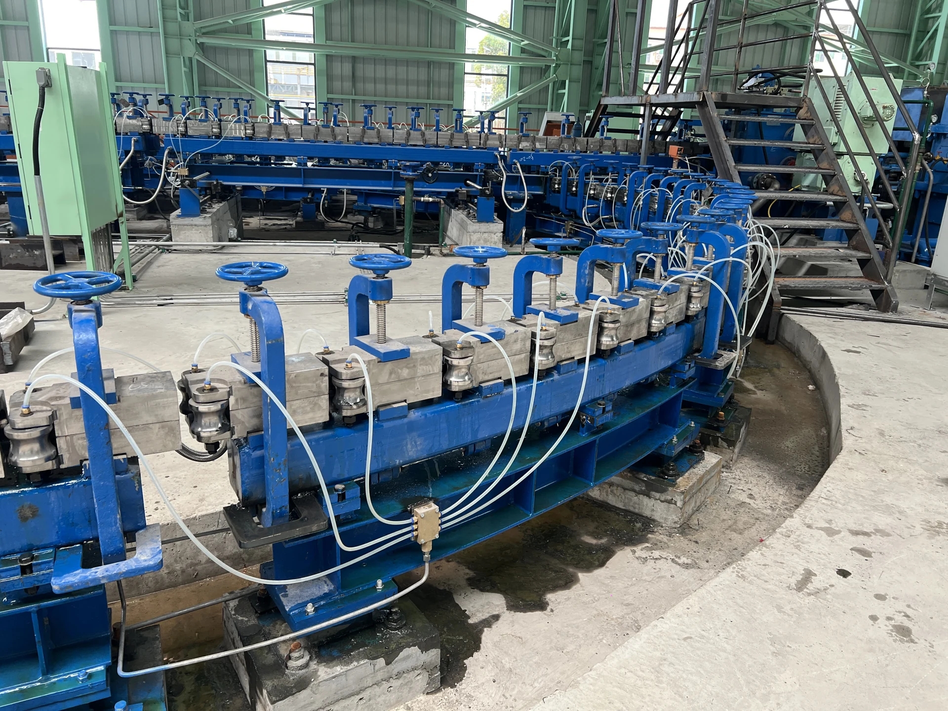
Make each transfer part of one guide path.
Guide troughs are used along bar and wire rod production lines to connect successive processing stages. In water-cooling sections, their position and function depend on the cooling-line design.
Connect the entry and exit positions
Set the guide passage against the mill centre line and the adjacent equipment. Check each transition for alignment and clearance suited to the product being rolled.
Coordinate guiding with the cooling layout
Consider the Guide Trough, water boxes and connecting pipework together. The mechanical guide provides the product path through the area where the cooling equipment operates.
Make adjustment and inspection part of the plan
Identify the adjustment positions and the space needed to check guide surfaces, fastenings and alignment. Record the setup used after a product change or maintenance work.
Plan around the passage, the interfaces and the mill team.
BOYE’s installation photographs show the guide sections, handwheel adjustment positions and associated connections. The final guide arrangement is reviewed against the actual plant layout.
Establish the alignment reference
Confirm the entry and exit centre positions and centre height before setting the guide sections.
Check the transfer points
Review the passage from the preceding equipment, through the guide, and into the following unit. Confirm the required product clearance at each interface.
Allow for maintenance and return to service
Include room for guide inspection, adjustment and connection checks. Use an agreed reset procedure after maintenance or a change of product size.
Start with the rolling conditions and site dimensions.
A useful guide-trough proposal starts with the route the product must follow. Existing layout drawings and photographs help define the guide arrangement and installation work.
| Product and process | Steel grade, product size and line speed. |
|---|---|
| Pass-line dimensions | Installation position and pass-line dimensions. |
| Trough and interfaces | Trough length, profile and mounting interfaces. |
| Adjacent equipment | Cooling-water arrangement and adjacent equipment. |
| Inspection and replacement | Access for inspection and replacement. |
Keep the guide setup visible in your operating records.
Use the mill’s own records to assess the installation. Compare the same product range and rolling conditions when reviewing guiding issues or maintenance work.
Track guiding interruptions
Record where passage problems occur and the time spent clearing or investigating them. This helps identify the transfer points that need attention.
Record alignment and reset steps
Keep the setup reference for each product range. Record the checks and adjustments made after a size change or before the line returns to service.
Inspect surfaces and connections
Check wear at guiding surfaces, the condition of fastenings and alignment between sections. Use those observations to plan maintenance.
Pair the guide path with the cooling equipment.
The Guide Trough provides mechanical guiding and connection between equipment. The Water Box applies cooling water; the wider control system coordinates the cooling process.
Discuss Your Application
Send BOYE your mill layout, operating requirements and existing trough drawings or photos to discuss a suitable configuration.
Email: xjyou@boyeglobal.com