
Technical Insights
How a Closed-Loop Cooling System Works
A closed-loop cooling system links the measured temperature of the rolled product to the water applied in the cooling section. For bar and wire rod mills, the aim is to keep the product on a defined temperature path as production conditions change.
Start with the temperature path
The process team first defines the temperatures needed at the relevant production stages. Steel grade, chemical composition, product size, rolling speed and required properties all belong in this discussion. A temperature target is meaningful only when its measurement position and operating conditions are clear.
Cooling settings also need to reflect what happens after the water section. The chosen rolling and cooling route should support the required metallurgical structure and finished product properties. During commissioning, temperature records are assessed alongside material tests.
Measure a usable signal
An infrared pyrometer provides the temperature feedback used by the controller. Its position, field of view and optical condition affect the reading. Fluke Process Instruments identifies target size, environmental conditions and emissivity as key factors in infrared measurement. A clear view of the product and an appropriate sensor setup therefore form part of the control design.
Record where each sensor is installed and how its signal is checked. The control logic should recognise when the product is present, when a reading is valid and how to respond to missing feedback. Validate that the instrument is reading the intended part of the product.
Turn feedback into a water command
- 1. MeasureRead the product temperature.
- 2. CompareAssess it against the process target.
- 3. AdjustChange the cooling water command.
The controller compares the measured temperature with the target and sends a command to the regulating equipment. The result is measured again, completing the loop. The settings must account for the time between water application and the downstream temperature reading, as well as changes in rolling speed and inlet conditions.
Valve position feedback helps operators see whether the requested movement occurred. The resulting water flow also depends on the valve, pipework and available water pressure. Commissioning needs to connect the electrical command, physical valve movement and observed cooling response.
Connect the equipment to its role
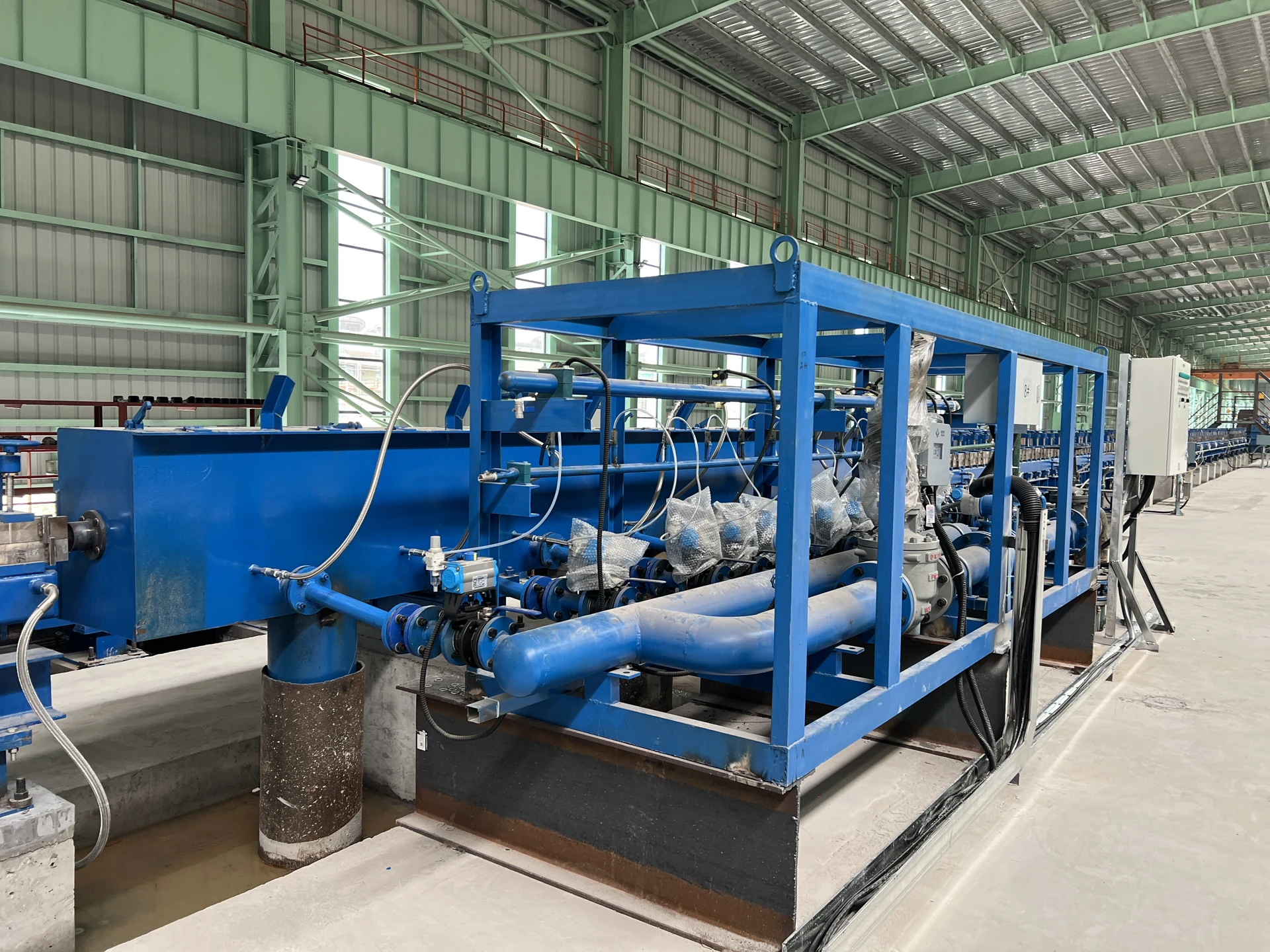
BOYE’s product materials describe a cooling arrangement that combines temperature acquisition, control logic and servo water regulation. A Water Box delivers cooling water to the rolled product; a Guide Trough supports guidance through the cooling section. The All-Electric Servo Valve Station brings regulating and on/off valve functions into the water control arrangement. The PLK Infrared Pyrometer and HMD-S8W Hot Metal Detector provide measurement and product-presence signals.
Verify the process result
Check representative grades and sizes, including operating transitions and the product head and tail. Retain temperature trends, water system conditions and product test records so that deviations can be traced to their cause. Where alloy reduction is a project objective, it is evaluated as a result of the complete composition, rolling and cooling process, with the required properties verified for the agreed steel grade.
For examples of control interfaces, operating records and reference compositions, see the closed-loop cooling application references. The reference page describes the limits of the available data.
Discuss your cooling project
Share your product range, line layout and temperature records with the BOYE engineering team.
xjyou@boyeglobal.com ↗